Presentation boards describing my design for an interactive performance space in Odense have been finished, and can be viewed by clicking on the image below.
Presentation boards describing my design for an interactive performance space in Odense have been finished, and can be viewed by clicking on the image below.
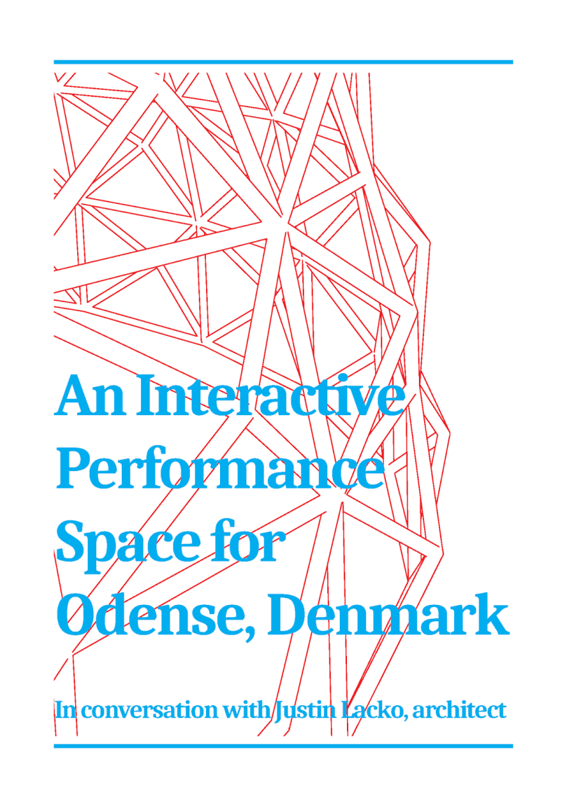
The following article presents my semester project as an interview with myself, the architect, after the project has been completed. It presents the project in a mostly chronological order of work done in the semester, starting with the site analysis and moving into the interactive elements and then the form.
The article has acted as a tool for reflection on my work, and also to prepare for the final presentation of the project. During the writing process I found myself asking questions about my work as a prompt for content creation. Presenting the project in the form of an interview allows me to speak honestly and in a direct manner, as if I had the opportunity to engage directly with the reader.
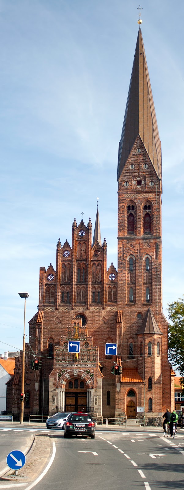
The most striking feature of the new city plan for Thomas B. Thriges Street in Odense, Denmark is also the most unnoticed. Beneath the collection of new buildings and squares is a massive underground parking area designed to maximize usable surface area and eliminate the presence of the automobile from the city square.
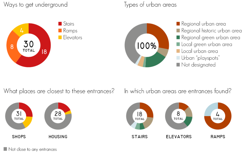
How we move from above to below provides a starting point to examine how these transitions occur. Is it a straightforward movement, such as a simple staircase, or can we create an articulated design that captures the essence of our vertical travel? The following pie charts show that the most common way to access the underground are by stairs, and the most significant places they lead to are regional urban areas.


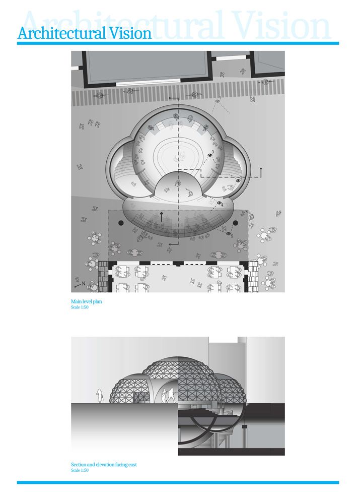
Sheets 1-3
I spent last week researching the area around Thomas B. Thriges Street in Odense as a means of locating where I wanted to situate my project. Having a previous interest in information graphics, I focused on the data concerning how people get from the underground parkade to the street level and used it to create a series of pie charts and a usage diagram.
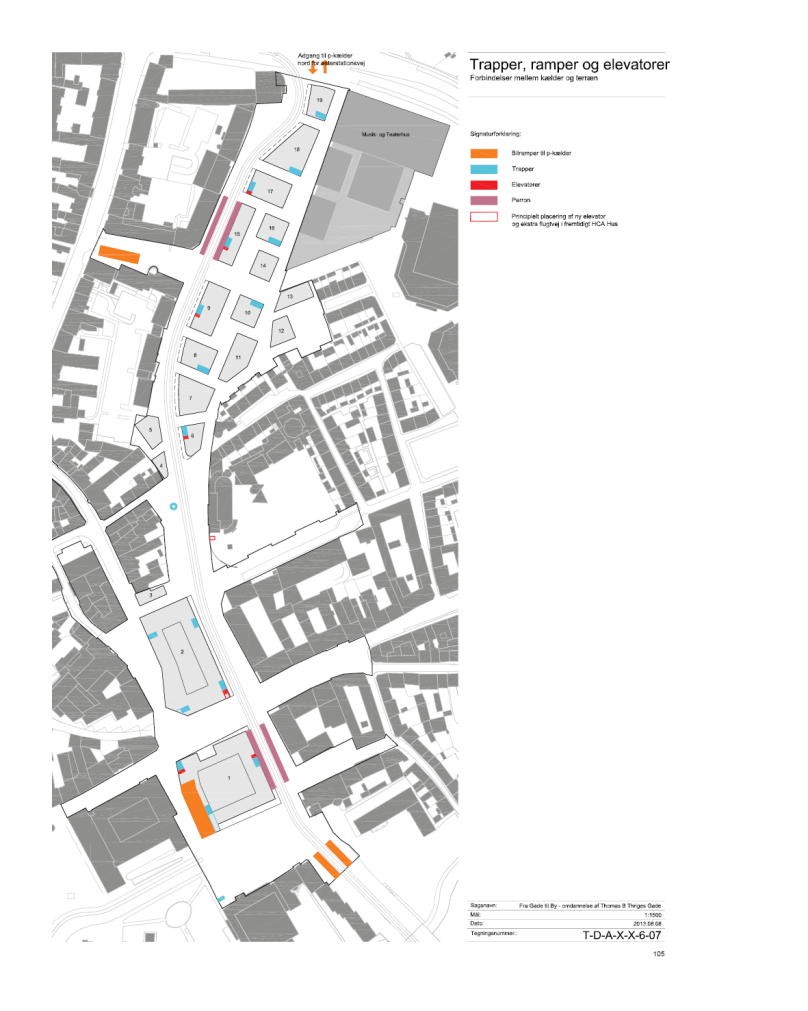
The data shows that one of the most common ways to move from underground to above is via stairwells located throughout the site, and that most of these stairwells are located around areas designated as “regional urban areas” – this is the Musikhuspassagen, Overgade and Albani Torv areas:

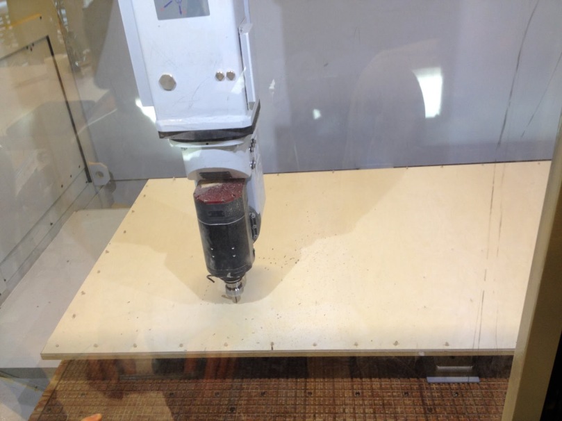
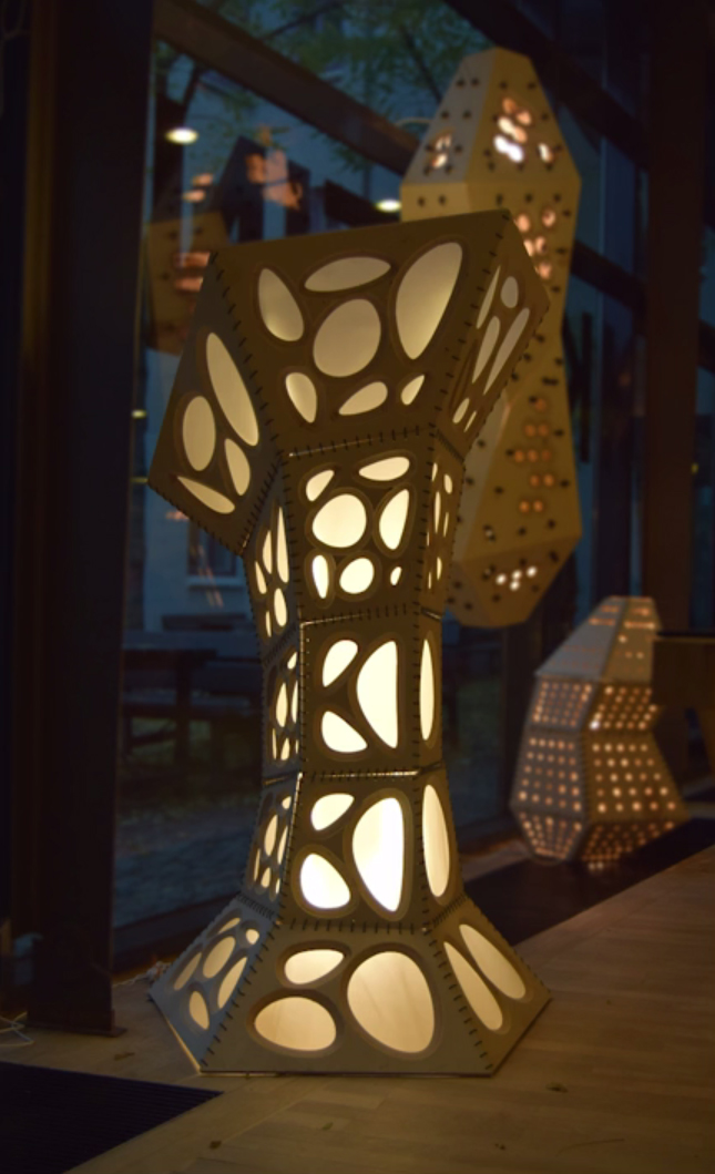
The school has a large 5-axis CNC machine that we used to cut out the pieces of the lighting object. The process actually took longer than expected due to the large number of binding holes. Average cut time was probably around 45 minutes – 1 hour per sheet. In the first pass, the CNC drilled the binding holes.


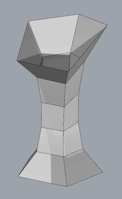
Conclusions: The workshop gave students a chance to use the school’s CNC machine to bring a computer-generated form into physical space. We accomplished this in the short time frame of only five days, with a few sacrifices: the tight timeline meant that we could not test out our ideas, so we didn’t actually know how the final design would hold up in terms of assembly and fit.
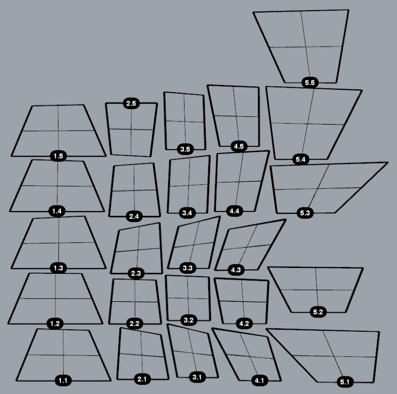
The design process partially suffered from the inability to fully automate some processes of the parametric design. The patterns team provided us with the concentric lines to cut the contours all flattened on the z-axis, so we had to manually move each set of rings down 2mm each so that the contours would be cut correctly. We had to move our binding holes inward on each quad once we realized during a simulated cutting that they were too close to the edges.
Alphacam was mentioned a few times by one of the workshop instructors as a “terrible” piece of software to handle CNC milling. There were many occasions where only the instructors knew the right settings needed. I am confident that I could not cut anything on my own, despite the CNC machine being free for all students to use.
It was very difficult to find the right combination of settings in our Grasshopper sketch that would produce truly planar quads for cutting. There was a tolerance issue of +/- 1mm all around, which greatly affected the edges of the quads. Instead of being made from a single planar edge, most of them had a bit of “warp,” associated with the edge being made from a double curve. It seems that there should be a better way to ensure that the final form is planar.
The binding holes turned out to be very snug, and in some cases the string wouldn’t fit through without the hole needing widening with a tool. In retrospect, we should have made larger holes. The binding process as we designed it was very time-consuming during assembly. A different assembly technique would have benefited the project.
The lighting object that our team produced was an excellent example of what you can produce on a CNC machine with a week of work. Further experimentation with the machine would result in projects with a higher degree of craft, and it would be worthwhile to experiment with other materials as the plywood had a tendency to splinter on the edges where the wood grain ran perpendicular to the cutting direction.
I’m not sure if I will use the school’s CNC machine in my own work yet, but it now appears a lot more accessible than it was before.
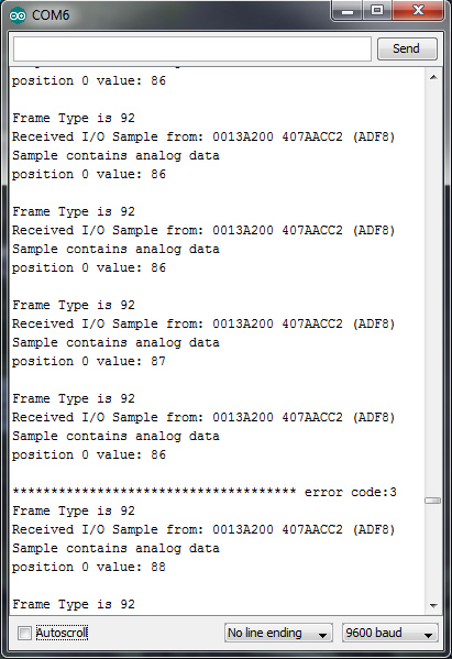
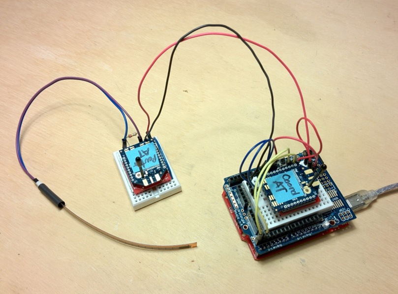
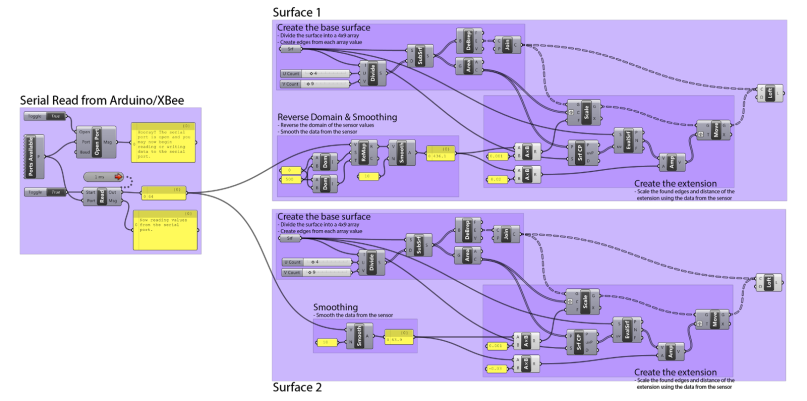
Recently I’ve been using Andrew Rapp’s XBee library for Arduino so that I can start to communicate with more than one radio module at a time. This is a crucial step, and as the screenshot below shows, now the code can also tell me the XBee’s address.
I found a great code example of how to display information from each XBee at this blog – it’s invaluable!
The next step is to take the data from each XBee and probably insert it into an array that gets passed to Grasshopper.
One of the Firefly devs actually responded to my earlier question and said I didn’t need the Firefly firmata on the Arduino if I was only using the Firefly serial read/write components. For now, this works, but I wonder if I will need to output data from Grasshopper to the Arduino at some point in the future. Possibly not, if the Arduino at the base station is only acting as an interface to the XBee coordinator radio. I will have to look into this.
void setup() {Serial.begin(9600);}void loop() {//make sure everything we need is in the bufferif (Serial.available() >= 21) {//look for the start byteif (Serial.read() == 0x7E) {//discard some bytes that we’re not usingfor (int i = 1; i < 19; i++) {byte discardByte = Serial.read();}//grab the two bytes that make up the analog value from the wireless sensorint analogMSB = Serial.read();int analogLSB = Serial.read();//convert to decimal to create the analog readingint analogReading = analogLSB + (analogMSB * 256);Serial.println(analogReading);}}}


You must be logged in to post a comment.